Since Fall 2017, I've been a part of Cornell Baja Racing, a student-led project team at Cornell that designs and builds an off-road racing vehicle for the Baja SAE collegiate competition.
Today I lead the ergonomics and composites subteam, which is in charge of the seat, steering wheel and body panels. In 2018, I was responsible for the design of the seat in addition to leading the team. In 2019, I am leading ergonomic integration with brakes, steering and frame using an ergonomic software called RAMSIS, as well as tutoring younger members.
Seat Concept
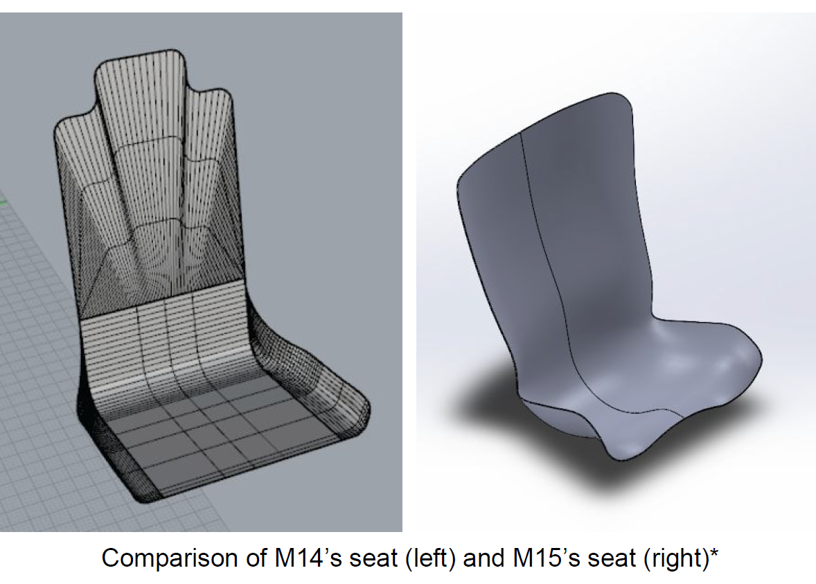
During my first year on Baja (for car model M14), I designed the first fixed seat the team had used in the past several years. This year (for car model M15), I developed three major design changes for the fixed seat after observing user interactions with the seat:
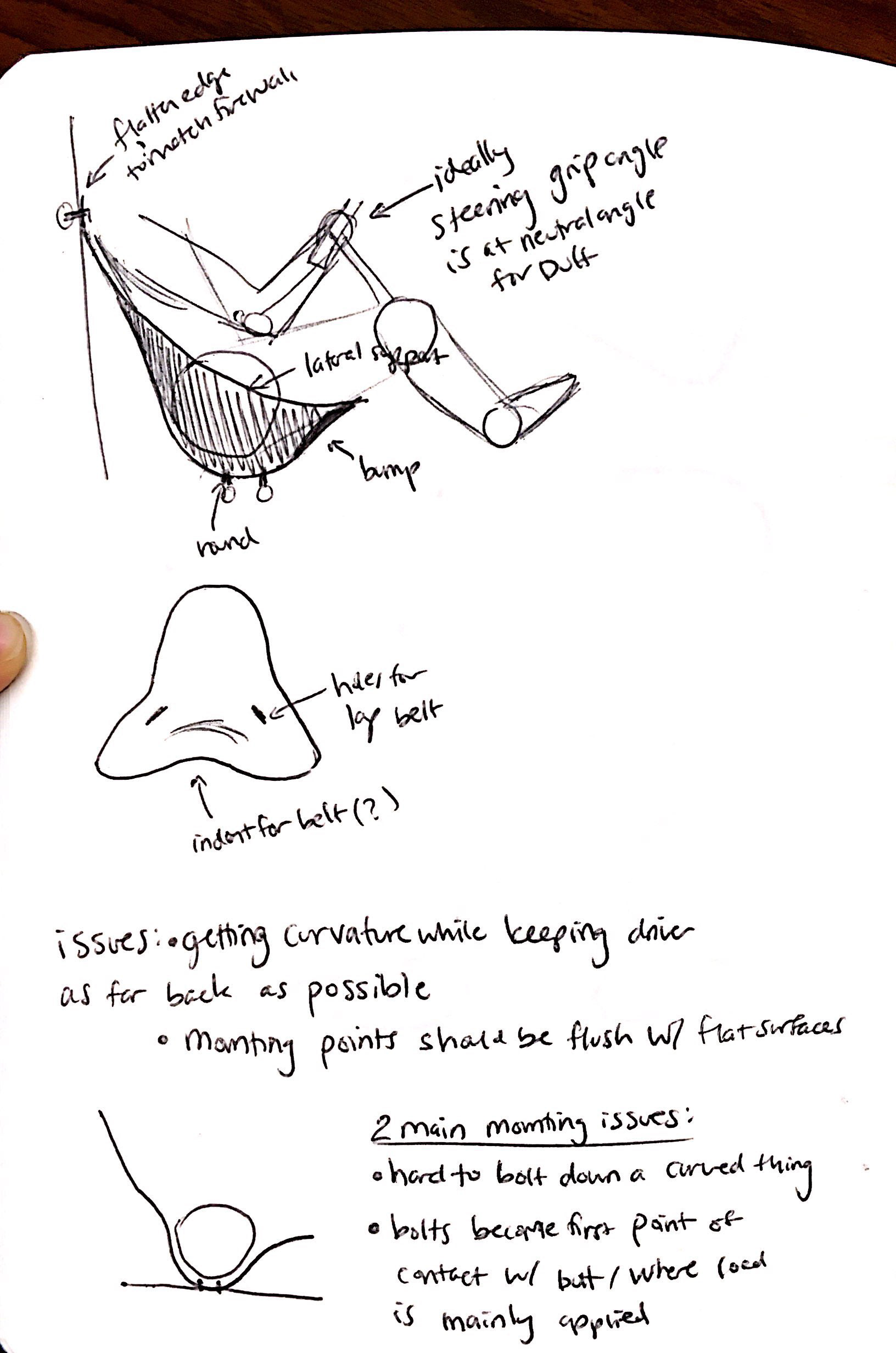
1. Lateral support
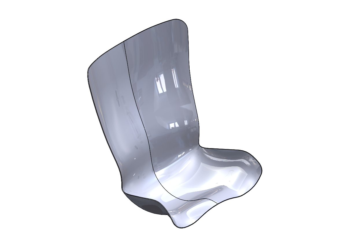
As seen in the comparison of these two CADs, M14’s seat did not have much material on the sides to assist with laterally restraining the driver. The edges of the seat sides were raised roughly 2 inches to increase lateral support.
As seen in the comparison of these two CADs, M14’s seat did not have much material on the sides to assist with laterally restraining the driver. The edges of the seat sides were raised roughly 2 inches to increase lateral support.
2. Built-in lumbar support
From observations during competition and drive days, the ergonomics team noticed that the lumbar pillow was rarely if ever used, except during tech inspection and design presentations at competition. This was most likely due to forgetting to put it on, or drivers feeling like they didn’t “need to use it.” Therefore, a slight lumbar curve (roughly 1 inch deep) was put in the seat to ensure lumbar support at all times.
From observations during competition and drive days, the ergonomics team noticed that the lumbar pillow was rarely if ever used, except during tech inspection and design presentations at competition. This was most likely due to forgetting to put it on, or drivers feeling like they didn’t “need to use it.” Therefore, a slight lumbar curve (roughly 1 inch deep) was put in the seat to ensure lumbar support at all times.
3. Under-hamstring support
One of our main drivers, Duff, mentioned that due to the flat bottom of M14’s seat, it is very easy to slide forward in the seat, with the anti-submarine belt being the first point of restriction. Therefore, M15’s seat has a slight upward curve under the hamstrings to prevent the driver from sliding forward, and providing a first point of contact that is not the anti-submarine belt.
One of our main drivers, Duff, mentioned that due to the flat bottom of M14’s seat, it is very easy to slide forward in the seat, with the anti-submarine belt being the first point of restriction. Therefore, M15’s seat has a slight upward curve under the hamstrings to prevent the driver from sliding forward, and providing a first point of contact that is not the anti-submarine belt.
Each of these proposed design changes was researched and verified to existing ergonomic literature (see report attached at the bottom of this page for full description).
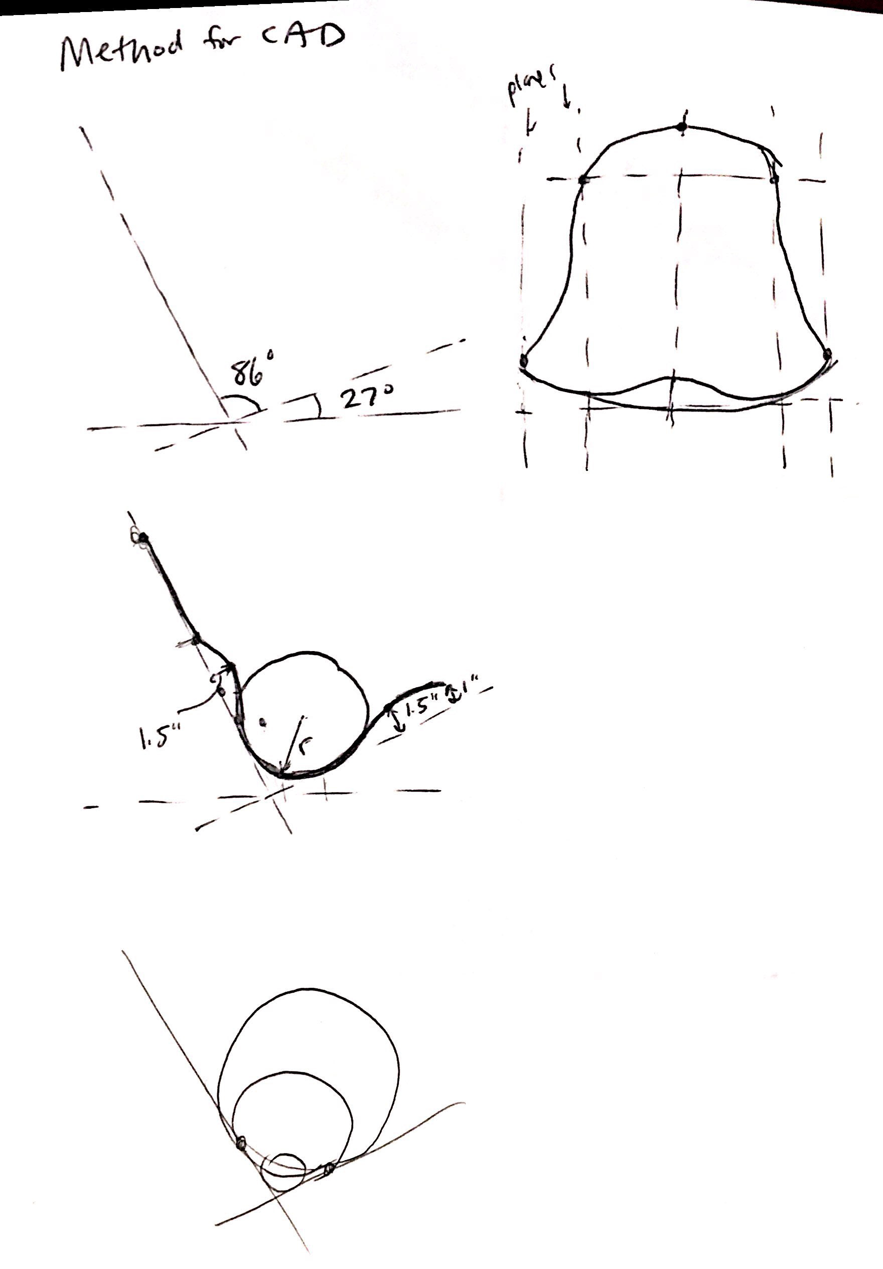
Design Method
The design of this year’s seat was highly focused on conforming to the driver’s body. However, the rules (as well as good ergonomic practices) dictate that the seat must fit the 5th-percentile female to 95th-percentile male. Our design goal was then two-fold: to fit our main driver, Duff, as well as possible, while still being usable and relatively comfortable for other sized drivers. To create a seat that conformed to our drivers bodies we needed the following information:
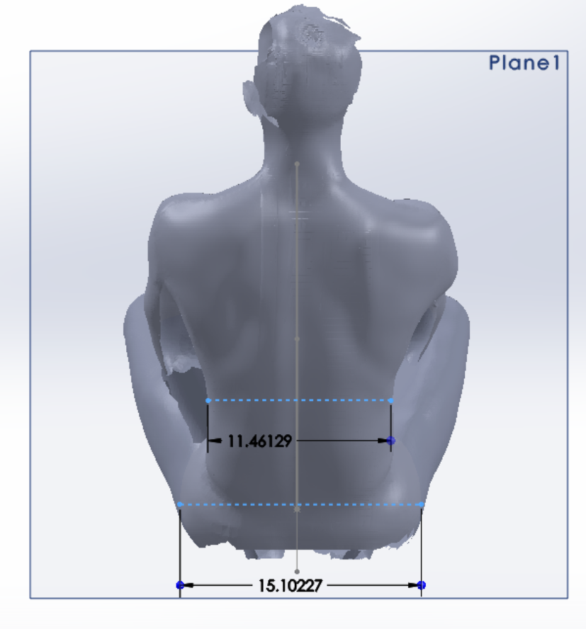
Lateral support → how wide are people’s hips?
Built-in lumbar support → what size lumbar indent do people have in their spine?
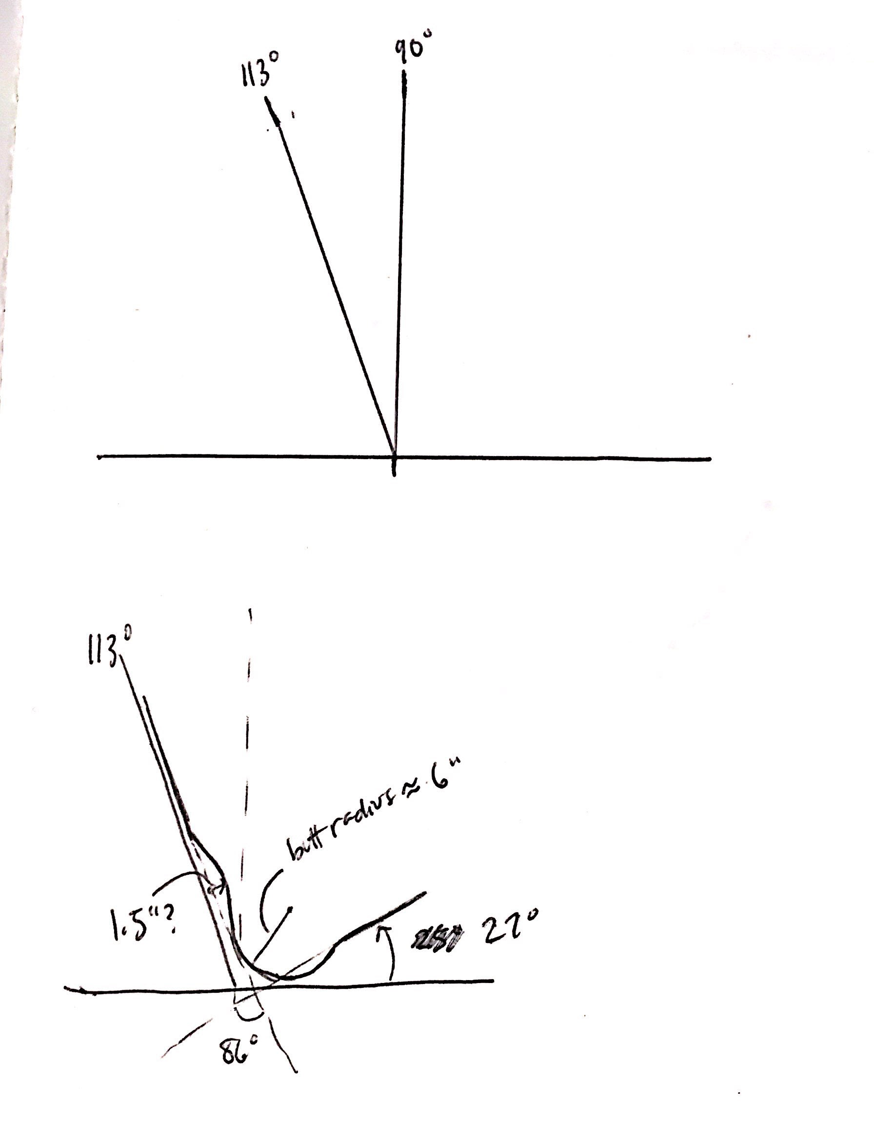
Under-hamstring support → what angle are people’s hamstrings with respect to horizontal when sitting in the car?
Height of the seat → what is the buttock-to-shoulder height when sitting?
Built-in lumbar support → what size lumbar indent do people have in their spine?
Under-hamstring support → what angle are people’s hamstrings with respect to horizontal when sitting in the car?
Height of the seat → what is the buttock-to-shoulder height when sitting?
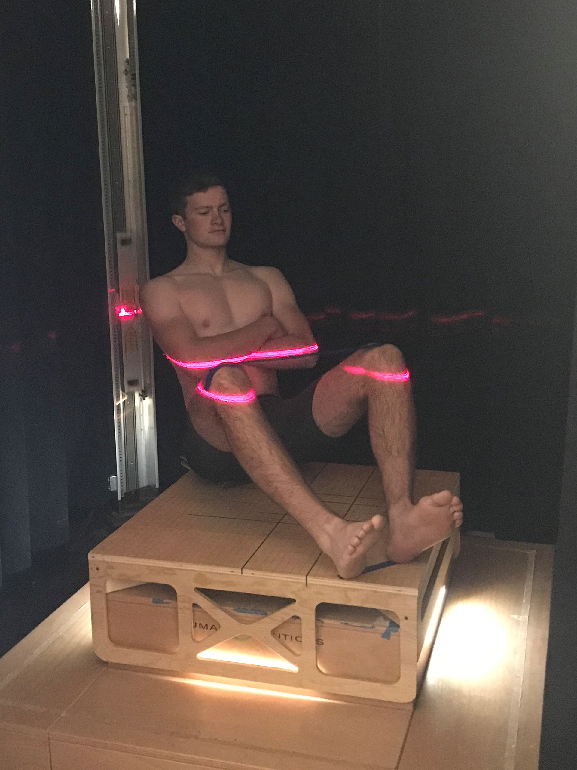
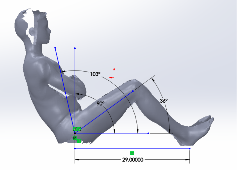
Our first attempt to figure out these dimensions was to use the body scanner at the Fiber Science & Apparel design department. The drivers were positioned in the scanner as if they would be sitting in the car. This method allowed us to get accurate measurements for the leg angles and driver heights. However, the drivers had to hold up their backs at roughly the angle they would be at, without any support, and therefore the angle we measured was not quite accurate.
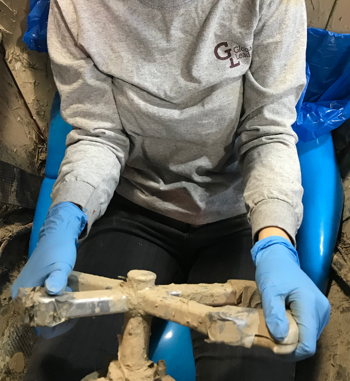
Our second attempt to obtain the natural angle people's bodies like to be at in the car was to use expanding foam. The drivers were seated in last year's car (M14), with expanding foam acting as a cushion. They were allowed to position their bodies however felt most comfortable in the car. The foam expanded and hardened, and then we brought the foam to the body scanner to obtain the shape and angles the drivers were positioned at.

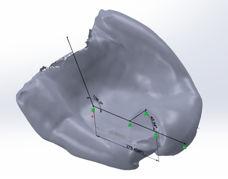
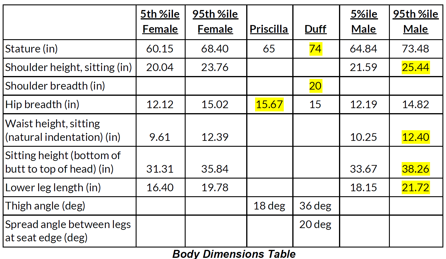
Ultimately, the body scans were more helpful than the expanding foam molds because the mold shapes were difficult to manipulate and measure in Solidworks. I chose the scans of a driver with larger seat bottom dimensions to be the leading guide for the seat curvature. To consider all body sizes, I created a chart with dimensions of the 5% and 95% percentile male and female, as well as the people we scanned. I modified each CAD spline to fit the largest dimension among the ones on the chart (highlighted in yellow).
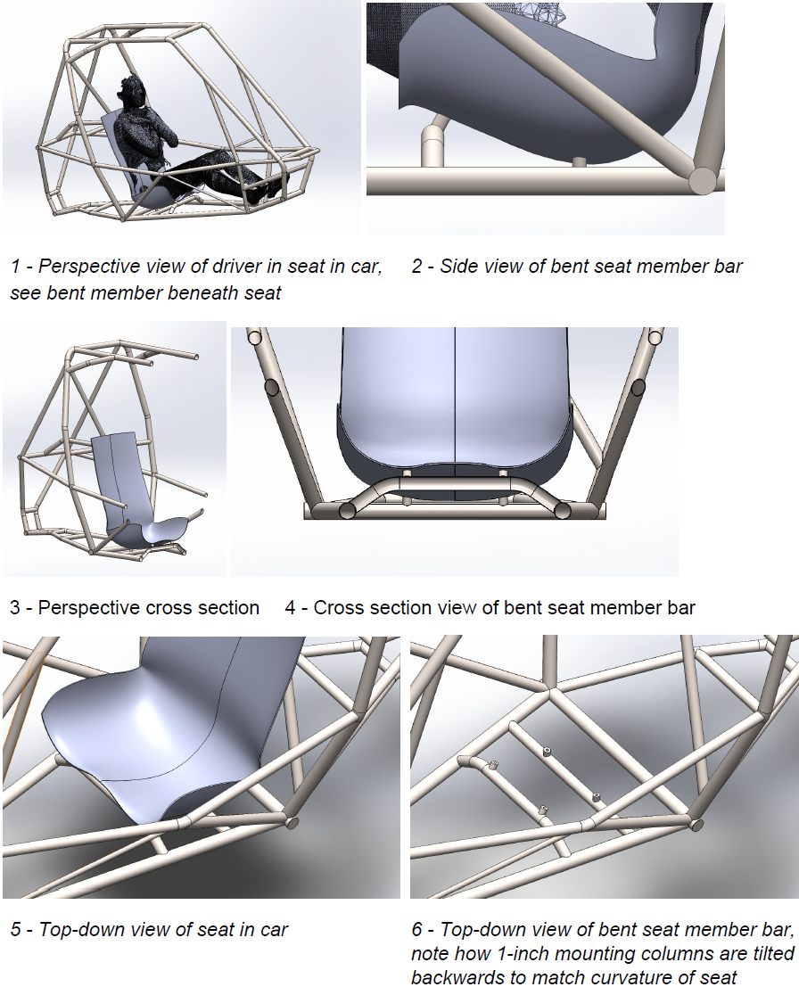
Integration with Frame
To account for the under-hamstring support in the seat (upwards curve), and the fact that
mounting points cannot be more than 1 inch from the seat, we bent one of the secondary members to reach up to meet the seat.
mounting points cannot be more than 1 inch from the seat, we bent one of the secondary members to reach up to meet the seat.
Manufacturing
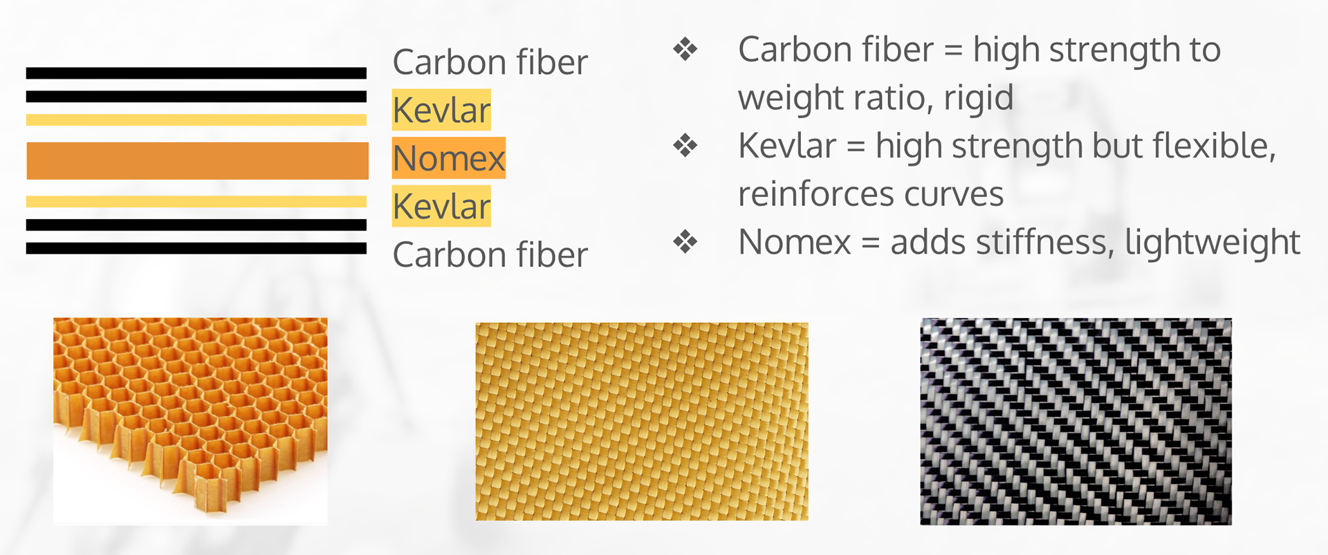
The seat is manufactured from carbon fiber, kevlar and nomex as described below.